SLR5500 Auxillary Connector

 |
| (Image credit: ZYTRAX Inc.) |
The pinout for the connector is as follows:
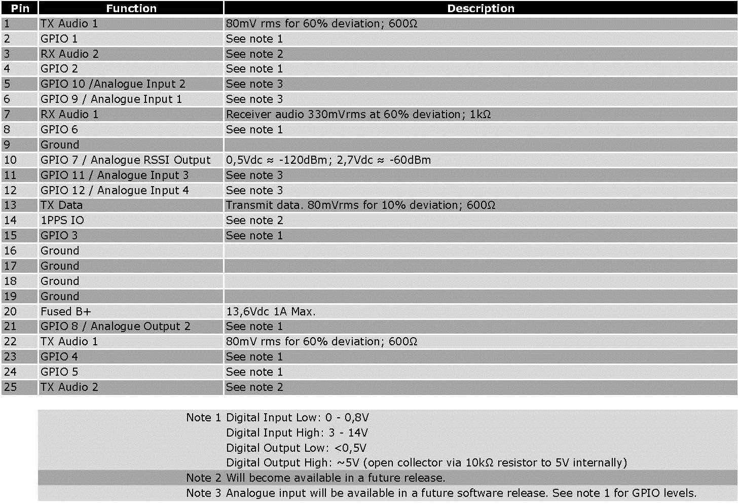

The following functions can be assigned to any of the GPIO pins:
- AC Power Failure. Changes state when mains is lost.
- Antenna Relay. Can be used to control a RF relay when the repeater is used as a base in a analogue dispatch system. Or can be used to control an external PIN-diode RF switch for ERDM operation.
- Channel Select. See my post on Channel Steering.
- CSQ Detect. Changes state when carrier is detected on an analogue channel.
- Disable. Will disable the repeater when triggered. Particularly useful if you are using the repeater in a hot-standby configuration.
- External PTT. This input will PTT the repeater (in analogue mode).
- FCC Type 2 Monitor. This is an input line, that when activated, prevents the repeater from keying up and from repeating inbound calls.
- Football Knockdown. This is an input line, that when activated, disables the receive and transmit operations of the repeater for as long as the pin is activated. CWID will not be transmitted while this option line is active. This is applicable to Single Site Digital mode and Repeater configurations only.
- Major Alarm. This output will change state when a major alarm is detected. Particularly useful if you are using the repeater in a hot-standby configuration. This would be connected to the Disable input of the standby repeater.
- Minor Alarm. Same as Major Alarm except this pin will change state when a minor alarm is detected.
- Monitor. This is an input line that allows the repeater operator to monitor an analogue channel. The repeater will unmute regardless of PL/DPL.
- PL/Talkgroup Detect. This output will change state when either the valid PL (or DPL) is detected (applicable to analogue mode) or if a Talkgroup Call is in progress (in digital mode).
- Repeater Knockdown. This is an input line, that when activated, will disable the internal repeat path of the repeater for as long as the pin is activated. An external device can then control when the repeater keys-up (applicable to Analog mode only).
- Reset. Triggering this line will reset the repeater.
- TX PL Inhibit. This is an input line that, when activated, will inhibit the transmission of PL/DPL when the repeater transmits.
- TX Power Level High. This is an input line, that when activated, sets the repeater to use the high power level for TX transmission. When de-activated, the repeater uses the low power level for TX transmission. Note that the repeater will reset before changing its TX power level.


Leave a Comment